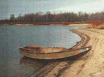
My own Roar2 has achieved that wonderful "old pickup truck" status.
Contents:
Contact info:
Jim Michalak
118 E Randall,
Lebanon, IL 62254Send $1 for info on 20 boats.
Jim Michalak's Boat Designs
118 E Randall, Lebanon, IL 62254
A page of boat designs and essays.
(1Jan00) This issue reviews the free Plyboats Demo design program. Next issue, 15Jan00, will present two Piccup Pram spinoffs.
WEBSITE ALERT...
If you are interested in free analytical boat design software go to http://www.plyboats.com/> (archived copy) and download the Plyboats Demo. I'll be discussing it in this issue if you care to follow along.
|
|
Left:
My own Roar2 has achieved that wonderful "old pickup truck" status. |
|
|
PLYBOATS DEMO REVIEW
I think Ray Clark's PLYBOATS program has been around since the early '90's and is basically a DOS program. As usual, I've never actually read a tutor book about this program, just played with it until I thought I had it figured out.
Plyboats does something that is very clever. Look at this graphic:
Focus on the five longitudinal blue lines, the sheer lines, the chines, and the keel line. Now look just at the starboard sheer line that I've marked. Imagine the three points that I have marked that form the two ends, and the point of maximum deflection of the line (which is at the boat's maximum beam). Imagine you had just those three points and sprung a batten through them and recorded the deflected shape. You would have defined the entire line and every point on it. Each of those five lines shown is defined by just three points so the entire hull shape here is defined by typing in the coordinates of fifteen points. That's it. That's how Plyboats works.
Plyboats is actually more versatile than that because it allows a total of eight lines, the two sheers, two upper chines, two lower chines, and two keel lines (in that the keel can also have curved sides), Plyboats also allows the use of several "tapered battens" such that the curves through the point can be varied so that you might make the ends more blunt or pointed than what would be produced by a constant section batten. I suppose there is a limitation in that all the lines must have their maximum deflection at the same section but that is seldom a factor.
I design by hand but essentially I try to design a boat in exactly the same way! Why? For one thing the curve of the batten bent through three points means there will be no kinks in the water flow lines and that the real pieces of wood in the real boat will by nature want to take a similar curve. I think it also means that the real wood will have no curvature at its extreme ends (unlike a hull defined by true arc lines) and that will make construction easier because those ends won't have be forced into a curve at the stem or stern, with almost no way to lock in that curvature. So I think this sort of design layout makes a superior boat.
Plyboats gets the information it needs to define your boat in a "question and answer" sort of way. There is no need for a mouse although it will make menu selection easier. But you can't "drag" lines and points around as with some programs. Let's look at some screens. (I found I couldn't capture and reduce the screens so I'm sorry for the large graphics.)
What we see here is the basic menu selected which will define the hull. I've selected the "New Design" option. But all that will do is walk you through all the items listed below it. If you have a design already in place (and Clark provides quite a few samples) you can tinker with it by selecting just the item you want to change. But keep in mind the information that the program is after - those three points for each line.
To start with the program will ask for a project name and then a total length. It also asks for the number of stations you want. The program will divide each line into that number of equal segments.
That done it asks you about where you want the section with the maximum beam (point B1 in the first figure). And it asks you for the maximum beam at the sheer line at that point (it has to be at that point).
Next Plyboats asks you for information about the rake or curve to the hull's ends under the heading of "Fore And Aft Curves". Let's look at the screen that defines the curve of the stem of the sample boat.
In the case of this simple boat, the chines and keel all end in the same point, at the bottom of the stem, such that the stem will be a simple straight line. But the two chines and the keel could all have separate end points and take on a curve (actually a series of short lines). The 3" dimension shown in this sample is measured inward from the end of the hull and thus this stem rakes aft 3" from top to bottom. (I'm pretty sure you can input a negative number here to get reverse rake if you want.) The sheer line always ends at the end of the hull as defined in the overall length. Later we'll have a chance to provide the stem with width or make a bow transom if we want to. If you click OK on this screen, the program takes you right to the same choices for the stern.
The next screen asks for the sheer heights and breadths. It already knows the location of the maximum beam and the maximum beam. So here you put in the sheer height at the point of maximum beam (measure from the lowest point of the keel which is taken to be the base point), how far the sheer sweeps up in the bow, and how far it sweeps up in the stern. You can input negative values to get the sheer to sweep down. Then it asks for the width of the sheer at the stem and at the stern. By now those sheer lines are totally defined. Here is the screen for the sample for the sheer up sweep:
The last line of "Curve Type" refers to the batten flexiblity that was mentioned earlier. I think 5 would be a standard non tapered batten. "55" means the same batten is used from bow to max beam and from max beam to the stern. But if, for example, you wanted an extra pointed bow with an extra blunt stern you might try typing in "46" with the "4" part being pointier than the "5" and the "6" part being blunter.
Next the program asks for the same info in the same way for the upper chine, the lower chine and the keel. In this sample there is but one chine so I put the same info in for both the upper and lower chine screens and they come out as one line on the screen. Here is one of the screens for the upper chine:
What you see here is that for this flat bottomed example the upper chine has a height of 0.0 which means at the point of maximum beam, it is on the base line. Then the bow and stern sweep up 6" so the boat has 6" of rocker. Remember also that the stem also rakes inward 3". When you click OK you will be taken right to another screen asking for the width of the chine at the stem, the station of maximum beam, and at the transom. Here is that screen for the sample boat:
So my sample boat has a maximum bottom width of 36" tapering to 1" wide at the stem and 24" wide at the stern.
The screens for the lower chine ask for the same information.
The keel info screen is a little different in that it won't ask for the height for the keel since its value at the maximum beam is taken to be the "zero" point for all vertical heights. But the program will ask for width and bow and stern rise. In the example I let the width value be zero so the keel appears as a straight line.
If you've been keeping track you will see that by now all of those fifteen hull defining points have been nailed down.
The last question the program asks for is the waterline or draft. It is easily changed later.
VIEWING...
Might as well view your work. Select View and see this menu..
If you select Sections you will see the end view of the hull with a cut at each section.
If you select Side View And Top View you will see this for the example boat:
There is a lot of information here besides the graphics. You can see the hull has been segmented into the number of sections you asked for and that the maximum beam section, shown in blue, is where you directed it to be. In the example there are 15 sections and the max beam was directed to be at section 8. Unlike the Hullforms program which asked for a cg location, Plyboats always presents a level hull and instead shows you the cg location which will give a level hull. It's marked as a dark triangle making it look like the balance point that it really is. Also in this screen is the waterline that you asked for plus the displacement of the lines with that draft and a calculated prismatic coefficient. If you want to know the displacement at a different draft you need only go back to the Waterlines input and type in a new number, click OK, and come back to this Side and Top View screen to see the new displacement value. You can go back into any of the choices in the Hull Design menu and change any of the geometry at any time and then check for the results on the Side And Top View screen.
The Heeled Displacement menu is pretty interesting. The program will ask you for an angle of heel and then calculate the righting moment, heeled draft, and wetted surface, etc.. But it never asks you for a cg location! Nor does it tell you where the assumed cg is (although it shows the assumed cg location in the graphic). So the righting moment calculations here aren't of much use. Too bad because it's a very difficult calculation and I think the program is doing it correctly except for the cg problem. I really hope Ray tinkers with Plyboats some day to give you an option of locating the cg. Also I'm pretty sure that the righting moments become invalid once the sheer line goes under the waterline but when that happens is quite evident in the graphics.
The next four options under the View menu show the hull in perspective as with this picture:
Next up is the Sail Design menu. I'm not an expert at this one but you can choose from a large selection of rigs and there are screens to lead you through it and ask all the things needed to dimension the sail rig. It responds with a picture with a lot of calculated data. Here is a resulting graphic for the the example boat:
Last comes the Utility menu of the program. In the demo program most of these functions are disabled. For example the demo doesn't allow you to print out the hull offsets or the graphics that you see above. In this menu you could also create a DFX file that could be read by a CAD program and allow to you transfer the lines for further detail work. The real Plyboats also allows a printout of the true shapes of the hull panels, an important time saver. Here the the plywood panel layout graphic for the sample boat:
Plyboats uses what I call the "Rabl's Triangles" method of expanding the panels. I call it that because the only time I saw the method described was in an old article by Sam Rabl reprinted in Boatbuilder Magazine. Each segment of the panel is divided into triangles, the true shape of each triangle is determined from the hull offsets, and the true shape of the panel reconstructed by laying out the true shape of each triangle one at a time. I use the same method with a homebrew spreadsheet and find it gives very good results, with no real need to follow any special rules about projections. (This is one area where the computer makes the nearly impossible into routine. Rabl wrote about his method before the days of computers, doing the expansions with hand drafting. But unless the hand drafting is done full size, or nearly so, small errors become huge errors by the time the expansion is done making the method fairly impractical by hand.)
NEXT TIME...
I'll present some Piccup Pram spin offs.
CAPRICE
CAPRICE, WATER BALLASTED SAILBOAT, 25' X 6', 900 POUNDS EMPTY
This one is brand new. It's a 25% enlargement of Frolic2, at least the main hull lines are. A straight "scaling" of an existing design hardly ever works perfectly for one reason or another. In this case I raised the cabin deck to get more headroom and had to shift bulkheads around to get some more living space. But still, Frolic2 was a very good starting place. In particular, the customer wanted more cruising volume than with Frolic2 but still wanted the rough water ablilities.
The hull shape of this boat goes back to my Toto canoe and my Roar2 rowboat. Both are quite good in rough water. The shape is close to that of a Swampscott dory, although these sailing versions have a wider bottom plank than I would have on a rowing dory. In addition I drew in water ballast tanks, four separate tanks totaling about 700 pounds of water, which should keep her on her feet. The water weight could be replaced by lead or iron if you didn't mind trailering the ballast around and you would pick up some extra interior volume. (I'd think that a sharpie hull with flat bottom and metal ballast would have a lot more interior room than Caprice, but would also be a lot more punishing in rough water.) I've also been concerned with rot in the water tanks because they are hard to dry out and very difficult to inspect and repair. Perhaps a swish of bleach or antifreeze with each fill will kill the rot bugs?
< WIDTH="524" HEIGHT="259">
The layout is pretty routine for a boat this size: The first two feet are open well for the anchors and wet stuff, followed by the bunk house for two, then the decked over raised cockpit that sheds water, followed by an open motor well.
The sail rig uses the balanced lug main that I like so much. The main mast is just 16' long setting 190 square feet of sail, one of the real advantages of this rig. It steps on a tabernacle which is off center enough that you could use the boat as a motorboat with the rig folded and still have the hatch openings clear. The small mizzen will steady the boat at anchor or while reefing the main. By my experience a mizzen sail is not the great self steering device as some claim - locking the tiller is usually more important in self steering. But the little mizzen makes anchoring a lot steadier and makes heaving to reef very reliable. Without it the boat will usually wander out of control if you are single handed and leave the tiller to reef the main. A real cruising boat will do well to have a mizzen, but a daysailer can do without.
Caprice uses a rather large pile of plywood with taped seam construction. Eight sheets of 1/4" plywood, nine sheets of 3/8" plywood, five sheets of 1/2" ply, and one sheet of 3/4" ply.
Prototype plans for Caprice are $35.
Prototype News
Some of you may know that in addition to the one buck catalog which now contains 20 "done" boats, I offer another catalog of 20 unbuilt prototypes. The buck catalog has on its last page a list and brief description of the boats currently in the Catalog of Prototypes. That catalog also contains some articles that I wrote for Messing About In Boats and Boatbuilder magazines. The Catalog of Prototypes costs $3. The both together amount to 50 pages for $4, an offer you may have seen in Woodenboat ads. Payment must be in US funds. The banks here won't accept anything else. (I've got a little stash of foreign currency that I can admire but not spend.) I'm way too small for credit cards.
Here are the prototypes abuilding that I know of:
Jonsboat: Greg Rinaca near Houston sent this photo of his completed Jonsboat, land bound until he rounds up a motor.
< WIDTH="350" HEIGHT="138">
Mayfly12: A Mayfly12 is going together up in Minnesota. The decks are on and he's into the sailing bits. By the way, the sailing bits on almost any sailboat large or small consume about half of the effort in labor and materials. Just when you thought you were about finished! (Just talked to the builder and the project is on hold until next spring while he moves into his new house.)
AF4B: A builder in Virginia is building AF4Breve, a 15.5' version of the 18' AF4. I tried to talk him into building the 18' version but he had two very good reasons to go shorter - a short trailer on hand and insufficient building space for the larger boat. The AF4B is essentially a "scrunched" version of AF4 but comes from a whole new set of drawings. The prototype is in the final building stages where the sanding and filling and painting seem endless. (Just heard anew from the builder. Seems his property and priorities have been temporarily rearranged by Hurricane Floyd. So progress on AF4B is now on hold.)
AF2: An AF2 has been started in Oklahoma that should be close to the plans. Bottom (double layer of plywood) is on and finished and the hull has been flipped upright by brute strength, no ropes or jacks used. See the flip at Rich's site. As I'm writiting this he is in the sand/paint stage and progressing very rapidly. This boat is far enough south that it could be launched during the winter.
Herb builds AF3 (archived copy)
Hullforms Download (archived copy)
Plyboats Demo Download (archived copy)
Table of Contents