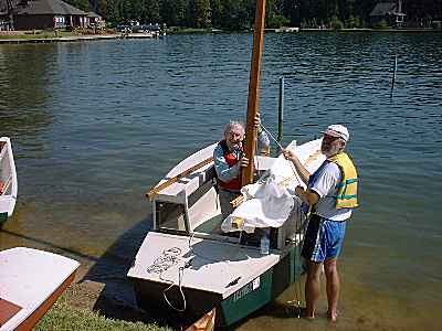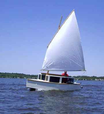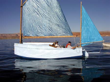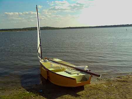
Ian Rogers built this pretty Family Skiff in England. Note that he used a daggerboard instead of the standard pivoting leeboard.
Contents:
Contact info:
Jim Michalak
118 E Randall,
Lebanon, IL 62254Send $1 for info on 20 boats.
Jim Michalak's Boat Designs
118 E Randall, Lebanon, IL 62254
A page of boat designs and essays.
(15 September 2012) This issue will complete the making an "instant" boat (originally aired on 1 March 2002). The 1October issue will start a series about calculating sail area.
THE BOOK IS OUT!
BOATBUILDING FOR BEGINNERS (AND BEYOND)
is out now, written by me and edited by Garth Battista of Breakaway Books. You might find it at your bookstore. If not check it out at the....ON LINE CATALOG OF MY PLANS...
...which can now be found at Duckworks Magazine. You order with a shopping cart set up and pay with credit cards or by Paypal. Then Duckworks sends me an email about the order and then I send the plans right from me to you.
Making A Hull 4
THE SAILING BITS...
If you are making a sailing boat you have a bit of work left. It's interesting to note that professionals claim to spend about half of the labor hours in putting a finish to the boat. But if I've found the labor and often the cost of a sailing rig is also about half the total cost of the project.
THE MAST STEP...
Mast steps vary but on smaller designs I prefer to use the solid chunk method. Well, almost. The mast shouldn't bear directly against the bottom of the hull, especially if the boat has no stiffeners along the bottom centerline. Why? Because the mast of a sailboat is almost always in compression, pushing down at the step and sometimes with a very large force. Also masts often rotate during sailing. So here is how I prefer to do the job:
What you see here is that the step is laminated in two pieces. The bottom bearing piece is usually 3/4" thick and the top piece is 1-1/2" thick. The top piece has the hole for the mast heel. You can cut it out with a band saw or saber saw usually. Same with the thinner bottom piece. The bottom piece should have, I think, a small slot to drain away any water that pools in the mast hole of the top piece. Cutting that drain slot is very easily done before the piece is attached to the top piece. Glue and nail the bottom piece to the top piece.
Now to install the step. Usually it fits into the intersection of the bottom and a bulkhead. Those two elements almost always meet at an angle. The step should fit right into that angle. Measure the angle on you hull and trim the front face of the step to match it. Fasten the step very well into the hull with lots of glue and stout nails or screws into both the bulkhead and the bottom.
THE MAST PARTNER...
Mast partners vary even more than mast steps! Some are just planks bolted across the boat's wales with a hole through for the mast. Some are thick plywood plates bolted and glued to the fore deck. Most of mine are lumber pieces bolted to a bulkhead like this:

Almost all are 1-1/2" thick lumber. Sometimes the partner lumber has to be pretty wide to accept the mast hole or slot, but also to space the mast the proper distance from the bulkhead. That might seem trivial but it is quite important. The proper dimension here will ensure the proper rake to the mast, and that puts the sail in the right position fore and aft, and that gets the handling of the boat just right. So the rake of the mast is one of the sacred things about your boat plans. (On the other hand, if your boat doesn't handle right, you can tinker with the mast rake to try to fix that. Rake the mast more aft and you should increase your weather helm. Rake it forward will decrease weather helm.)
Usually a mast partner like this is made in two pieces because that is easier. The hole for the mast becomes a slot that can be cut with a saber saw instead of needing a large hole saw. All that is easy enough. The real problem is bolting it to the bulkhead because the bolts need to be long, usually longer than the common drill. Here is how I do it. Once the step is made I drill the holes for the bolts through the step while it is on the work bench. Then I put the step in position on the bulkhead and spot the holes on the bulkhead with the drill. Remove the step and complete drilling the bulkhead holes. Long bolts are required and I don't know if there is much harm in making the bolt holes 1/16" or so oversized so that precise fitting isn't required. Long bolts are required and tighten the nuts well so that there is lots of friction between partner and bulkhead. In my opinion, this mast partner assembly is no place for wood screws - use through bolts.
THE SPARS...
The mast is pretty straight forward. I would always laminated my mast from several pieces of wood. If the design calls out for a 2-1/4" diameter mast I would use three laminations of 3/4" wood. For a 3" diameter mast I would use two 1-1/2" laminations. The practice of laminating will give you a mast that is much less likely to warp. With common lumber laminating also tends to spread out knots and flaws such that you won't get a big bad spot that goes clear through the mast.
Same with the yard and boom. If the design calls for a 1-1/2" square piece, then one laminated from two 3/4" pieces should be superior, although I must admit that using a single piece would be usually an acceptable temptation. On smaller boats, say less than 70 square feet of sail, I have used hand rail moldings, round and about 1-1/2" in diameter, as yards, and closet poles, round and about 1" in diameter, as yards. Don't use PVC pipe no matter how tempting. PVC is heavy and flexible compared to wood and really a poor choice. Aluminum tube makes very light and stiff spars. But I think wood is best for several reasons. One is that is it is traditional. Two is that it is cheap. Three is that it is quiet (compared to aluminum). Four is most important and that is that wood is bouyant! A small boat with a lug rig made of wood will not want to turn turtle when capsized because the yard and mast will act as outrigger floats when they hit the water.
You might try hollow masts and spars. I've made a few and in larger sizes hollow can be easier because you can work with 3/4" thick lumber with a normal saw. If you were to make your mast solid from say 3" thick lumber you will need a band saw or some special arrangement to trim it to shape since a normal circular saw won't cut that thick. On the other hand, in smaller spars you really won't save a whole lot of weight by making the spar hollow and I don't think heroic efforts will pay off here.
THE LEEBOARD...
The leeboard - always best to laminate it from thinner plywood to avoid warpage. So if the leeboard is to finish at 3/4" thick you should make it from two layers of 3/8" plywood or three layers of 1/4" plywood. What I like to do is to make one lamination exactly the right size and the others a bit oversized. Then apply lots of glue between the layers, place the layers on top of each other on a flat surface and tap light nails through the stack so that the layers can't slide around on each other. Then place something like concrete blocks on the stack of layers to appy pressure. Then walk away until the glue has set hard.
Trim the glued up leeboard blank to final shape. Then streamline the front and aft edges that will flow through the water. Don't just round the edges with a router bit. It doesn't have to be carved to a full airfoil shape but I would suggest something like this:
Here is how I do it. Clamp the trimmed blank to the workbench. Start the shaping on one edge with the coarsest rasp you can buy. As you carve through laminations you will find a nice line forms at each glue joint. Use these as indicators to keep your shaping true down the length of the edge. You will actually find it is fairly easy to do. When you get it roughly where you want it, smooth it all down with a belt sander. I don't own a power hand plane but would try it if I had one. I haven't found normal hand planes or drawknives to be very useful in shaping plywood - the rasp is my favorite tool here. Another useful tool might be a small disk sander with very coarse (20 grit!) paper in a drill.
As mentioned earlier about rudders, if your leeboard vibrates in use, streamline it some more.
My plans will show the position of the leeboard pivot hole but it might be prudent to hold off drilling it right now. Wait until the rest of the hull assembly is done so you can double check the proper operation of the leeboard.
THE LEEBOARD GUARDS...
This is the only tricky thing about leeboards but I think it is still a lot simpler than any centerboard or daggerboard case.
Here is the situation. The leeboard will be attached to one side of the hull, always at or very near to the widest beam of the hull. The leeboard pivots on a bolt that attaches to the lower leeboard guard. It will always be mounted such that it is parallel with the centerline of the boat. Usually it will be mounted vertically when the hull is lever, but not always - sometimes the leeboard is mounted parallel to the flared side of a hull. Is that bad? Most likely you would never notice the effect of the non-vertical leeboard.
So the first step in installing the leeboard is to locate the leeboard pivot point on the hull. The sail rig drawing will show where the pivot is supposed to be, both up from the bottom, and fore and aft on the hull. Level up you hull and mark where the pivot point should be. Then mark where the lower leeboard guard should fall on the hull. Like this:
Now to make a piece of wood to fit there. Usually on a smaller boat the lower leeboard guard is made from a piece of 1-1/2" thick lumber. Start with a piece that is a lot wider than the final width. We will trim off the outer face to be parallel with the hull centerline later. The biggest challange will be to cut the inside face of the guard so that it will fit tightly to the side and yet account for the flare of the hull's side and mount perpendicular to the leeboard.
Here is how I have done that. First I place the oversized lumber guard piece right above its final location, right against the wale and scribe the shape of the side there right onto the guard piece. So I'm using the wale shape in that area as a guide to the guard shape. Then I set a saw (a bandsaw works fine but so will a saber saw with a good blade) at an angle equal to the flare of the side. Then I saw to the scribed line at that angle. It should fit! Screw it into position temporarily.
Next we need to locate the outer face of the lower guard such that the leeboard will be parallel to the hull centerline and be vertical. The leeboard will bear on the wale. Place a level on the wale right at the leeboard pivot location like this:
Now place a long straight edge on the guard piece such that it its edge falls on the mark determined above and parallel to the hull centerline, like this:
Mark that line. That is where the outer face of the guard needs to be for the proper leeboard placement. Remove the leeboard and cut the face on that line. Trim the leeboard to its final shape. Drill the pivot hole. Glue and screw the lower leebord guard into position.
Now you can try mounting the leeboard to see if the pivot hole location is right.
Now to make the upper leeboard guard. Usually the best way to make this guard is to laminate it from several layers of thinner plywood. The upper guard will be glued and bolted to the wale. If the wale has a lot of sheer (curvature when viewed from the side) then the upper guard is sometimes best laminated clamped right on the wale so that it will start its life curved in the same way as the wale. As with the lower guard, start with a blank that is well oversized.
Once the blank for the upper guard has been glued up, place it on the wale and scribe the inner edge to fit against the hull. Trim that edge to shape and clamp the blank into position. Almost always on my designs the upper leeboard guard is attached to the underside of the wale. Locate the slot for the leeboard and mark the final shape of the guard. Remove it and cut it to shape.
When you cut the slot, make it a bit too wide. You don't want the leeboard to get stuck in the slot, and remember that the wooden parts will swell when wet.
Trial fit it with clamps, perhaps with the leeboard and its pivot bolt in place to check the workings. When you are satisfied, drill bolt holes to mount it while it is still clamped in place. Remove the clamps and apply lots of thick glue to the wale joint and bolt it in place. Take no chances with the strength of this joint.
THAT'S IT. Paint it and you are done!
Contents
Philsboat
PHILSBOAT, SAILBOAT, 15' X 5.5', 550 POUNDS EMPTY
Philsboat is essentially an IMB with the nose extended to a pointy bow. The width and multichine configuration are the same as IMB's. The cabin is 3" deeper because Phil is at least 3" taller than most of us. In a boat with a Birdwatcher cabin like this one added depth to the cabin makes it safer in that the righting forces in a knockdown are greater. That would be true of any boat if the center of gravity did not move with the cabin roof but with the normal cruiser adding depth to the cabin also means raising the crew deck up so the folks can see over the raised cabin. And that means the CG is elevated too, and then all bets are off concerning self righting. But with a boat like Philsboat eveyone rides down low inside looking out through the windows.
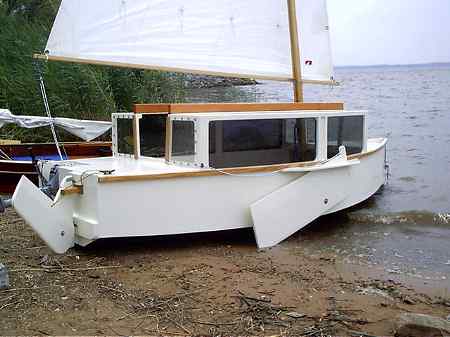
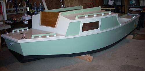
Here is a photo of Bob Williams' IMB:
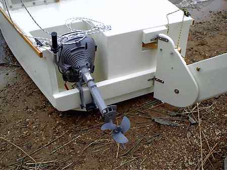
In addition to the pointy bow and added headroom I added what I hope is a serious motor mount. Probably 3hp will drive it as fast as it will ever go and that at part throttle. But the motor well gets to looking pretty large even for such a small motor. For one thing it must be deep to put a short shaft motor on a deep stern like this so I ran it straight down to the boat's bottom. Working on the motor down it its well will be about impossible and you might need to keep an eye on your knuckles when you pull the starting rope. And the well must be surprisingly wide to allow the motor to swivel in steering although the usual case here will be to keep the motor locked straight ahead and steer with the tiller. The wide well pushed the rudder off center and you need a crooked tiller or rudder linkage to make it all work. I opted for a simple but crooked tiller.
I also added low seats like those I saw added to the two IMB's that came to the Lake Conroe Messabout. Pretty much the same as what I have in Scram Pram where the seats do double duty as water ballast tanks. Philsboat seats could easily be converted into water ballast tanks also but the IMB capsize tests imply the ballast isn't needed.
The sail rig uses a balanced lug, 113 square feet and the same as that of a Bolger Windsprint.
Philsboat uses taped seam construction. Five sheets of 1/4" plywood, five sheets of 3/8" and three sheets of 1/2" plywood.
Actually the size and material list for Philsboat are about the same as that of Scram Pram. So which boat would be better? Take Philsboat if you are a pointy bow guy. It should be better in really rough water. On the other hand Scram is wider and roomier. It has a flat step through bow that will splash and spit in rough water but makes beaching a very nice experience.
Update, 2007. Chris Feller completed his Philsboat, probably the first prototype completed, and brought it to the 2007 Rend Lake Messabout. Very well made and to plans except he used the 91 sq ft lugsail he had on hand for his AF3, with some mast rake changes he calculated with his "sail area math". Sailed correctly rigtht off the drawing board, so to speak. We had a chance to use it for a few really nice days. In a good sailing breeze, say 10 to 15 knots with occasional whitecaps, our gps bobbed between 5.5 and 6mph for two hours of reaching as we crossed back and forth on the big lake. When I used the Philsboat I thought it was probably just as easy to enter from a beach as the blunt bowed Scram. The front deck is about 2' high so you can sit on it and swing you legs around onto the deck and then into the cabin.
Chris is a big boy but there was plenty of room inside for the two of us and more. Rumor has it that at the campsite the night before Chris slept in the Philsboat on the trailer with an airconditioner in the front hatch plugged into the campsite power. So the boat is plenty big in the way most people would use it.
The stern layout has the motor in a small well to one side and the rudder offset to the other side to give the motor room to swing. There is no linkage to the tiller, the tiller is simply "unstraight" so that is falls on centerline at the skipper's hand. Seems to work well and is quite simple. Chris uses a 2hp Honda which has a fairly large cowling for its size and must be rotated 180 degrees to grab reverse. He said the motor well size is a bit too small for that. Karl James had the same problem with his Jewelbox a long time ago and simply cut away the side of the hull in top of the motor well region - after all it is just there for looks. Chris said he tried the boat under power and found it went 6 mph max, just like under sail. No surprize to me. My Birdwatcher also maxes out at 6mph under 3hp and under 5.5 hp. This sort of hull will only go so fast. Add more power and you just dig a deeper hole and make a bigger wake - you won't go faster. But sometimes more power is nice on a windy day.
(As an update, Chris has brought his Philsboat to several more Rend Lake meets. In 2008 the meet was very windy and Philsboat got a full windows wet knockdown with Chris and Tom Hamernik on board. She self righted with no issues and they kept right on sailing, but Chris confessed he has 100 pounds of lead shot under the seats. Also he is using a 3hp vintage Johnson which he says is quieter and smoother than the Honda.)
You might recall from the Prototypes section recently that there was another Philsboat being built in California. That one last I heard was about to be launched. Has more changes from blueprint than Chris's boat but still is pretty true to form. Seems to be known as Bumble and made by Rex Meach.
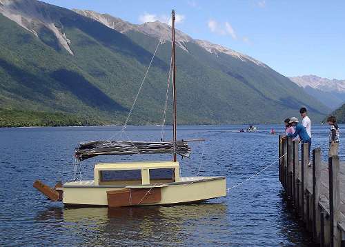
And in New Zealand Rob Kellock has been sailing his with a junk rig. He has been knocked down a couple of times and self righted as planned:
Plans for Philsboat are $45.
Prototype News
Some of you may know that in addition to the one buck catalog which now contains 20 "done" boats, I offer another catalog of 20 unbuilt prototypes. The buck catalog has on its last page a list and brief description of the boats currently in the Catalog of Prototypes. That catalog also contains some articles that I wrote for Messing About In Boats and Boatbuilder magazines. The Catalog of Prototypes costs $3. The both together amount to 50 pages for $4, an offer you may have seen in Woodenboat ads. Payment must be in US funds. The banks here won't accept anything else. (I've got a little stash of foreign currency that I can admire but not spend.) I'm way too small for credit cards.
I think David Hahn's Out West Picara is the winner of the Picara race. Shown here on its first sail except there was no wind. Hopefully more later. (Not sure if a polytarp sail is suitable for a boat this heavy.
Here is a Musicbox2 out West.
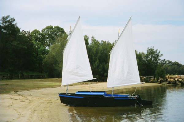
This is Ted Arkey's Jukebox2 down in Sydney. Shown with the "ketchooner" rig, featuring his own polytarp sails, that is shown on the plans. Should have a sailing report soon.
And the Vole in New York is Garth Battista's of www.breakawaybooks.com, printer of my book and Max's old outboard book and many other fine sports books. Beautiful job! Garth is using a small lug rig for sail, not the sharpie sprit sail shown on the plans, so I will continue to carry the design as a prototype boat. But he has used it extensively on his Bahamas trip towed behind his Cormorant. Sort of like having a compact car towed behind an RV.
And a Deansbox seen in Texas:
Another prototype Twister is well along:
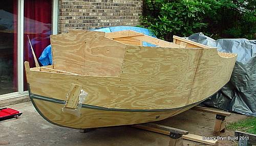
And the first D'arcy Bryn is ready for taping. You can follow the builder's progress at http://moffitt1.wordpress.com/ ....
AN INDEX OF PAST ISSUES
A NOTE ABOUT THE OLD WAY BACK ISSUES (BACK TO 1997!). SOMEONE MORE CAREFUL THAN I HAS SAVED THEM. NOW IT IS A QUESTION OF REINSTALLING THEM IN AN ACCEPTABLE FORMAT.
1oct11, Boat Costs, Larsboat
15oct11, Sail Area Math, Jonsboat
1nov11, Sail Oklahoma 2011a, Piccup Pram
15nov11, Sail Oklahoma 2011b, Caprice
1dec11, Taped Seams, Trilars
15dec11, Bulkhead Bevels, Sportdory
1jan12, H14 Rig, Olive Oyl
15jan12, Knockdown Recovery 1, DarcyBryn
1feb12, Knockdown Recovery 2, Caroline
15feb12, Underwater Board Size, IMB
1mar12, Underwater Board Shape, Paddleplank
15mar12, Underwater Board Shape2, Frolic2
1apr12, Underwater Board Shape3, Marksbark
15apr12, Rowboat Setup, Toon2
1may12, Electric Boats 1, Blobster
15may12, Electric Boats 2, Electron
1jun12, Messin With Motors, AF4
15jun12, Rend Lake 2012, Toto
1jul12, Prop Thrust, Brucesboat
15jul12, Making A Hull1, Mikesboat
1aug12, Making A Hull2, Paulsboat
15aug12, Olympic Thoughts, Cormorant