Jim Michalak's Boat Designs

118 E Randall, Lebanon, IL 62254


A page of boat designs and essays.

(15May2011)This issue will start a short series on how I take a stab at determining sail area. The 1 June issue will continue the topic.

THE BOOK IS OUT!

BOATBUILDING FOR BEGINNERS (AND BEYOND)

is out now, written by me and edited by Garth Battista of Breakaway Books. You might find it at your bookstore. If not check it out at the....

ON LINE CATALOG OF MY PLANS...

...which can now be found at Duckworks Magazine. You order with a shopping cart set up and pay with credit cards or by Paypal. Then Duckworks sends me an email about the order and then I send the plans right from me to you.

MESSABOUT NOTICE:

THE REND LAKE MESSABOUT WILL TAKE PLACE ON JUNE 10 and 11 AT THE PINTAIL LOOP OF THE NORTH SANDUSKY CAMP GROUND AT REND LAKE IN SOUTHERN ILLINOIS. USUALLY THE SANDUSKY CAMP GROUNDS MIGHT BE FULL FOR THAT WEEKEND. BUT SOME OF OUR BOATERS HAVE RESERVED SOME OF THE SITES THEIR SO YOU (AND I) MIGHT PASS THAT WAY FIRST SINCE SEVERAL TENTERS CAN SHARE A CAMPSITE. IF NOT, THEN I WOULD TRY THE WAYNE FITZGERRELL STATE CAMPGROUND WHICH IS ON THE MAIN CAUSEWAY LEADING TO SANDUSKY. THEIR WEBSITE SAYS IT IS STRICTLY FIRST COME FIRST SERVE, NO RESERVATIONS ALLOWED. IT IS A VERY QUICK DRIVE FROM THERE TO SANDUSKY. HOPE TO SEE YOU THERE!
Left:

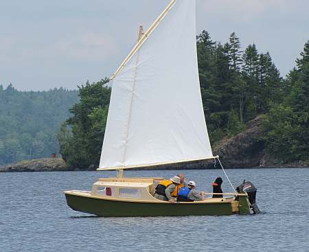
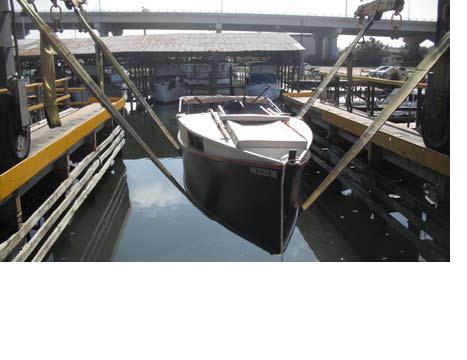
Rene Vidmer's far flung AF4b gets an oversized launching in Pensacola this time. Let's review: New York, up through Canada and the Great Lakes, down the Illinois River, down the Mississippi River, up the Ohio and the Tennessee, down the Tom Bigbee, along the Gulf Coast, then up the Suwannee, a portage across the Okefenokee Swamp, then up the St Mary's to Folkston, Ga where it now awaits a fresh motor!


Contents:


Contact info:

jim@jimsboats.com

Jim Michalak
118 E Randall,
Lebanon, IL 62254

Send $1 for info on 20 boats.


Contents


Sail Sizing

GENERAL...

This essay is based on an old essay, very old by internet standards, written in Feb 1998. I'm changing it around a bit and adding things that were learned over the past 13 years, but the basics are still the same.

The question that always comes up is "How much sail area do I put on a boat??" To me the secret here has nothing at all to do with placing a pretty sail rig on the side view of the hull. That's about the last thing you do. The secret is first to establish the stability of the hull, which is determined almost totally by the cross sections of the hull, their shape and width in particular. So one might ask, "How can you put a Sunfish rig on an 8' Catbox when the Sunfish was twice as long?" The answer is that the Catbox is wider and squarer than the Sunfish and has walk around stability, something the narrower but longer Sunfish doesn't have. In a way I'm thinking the length of the hull has nothing to do with the stabiltiy of the thing except that long hulls are heavier than short hulls and the weight figures directly into the stability. Don't get me wrong - long hulls can be a lot faster than short hulls, more seaworthy and roomier, so think long before you think short. But if you are trying to adapt a certain sail plan to a new hull you don't need to think about length hardly at all.

GETTING DOWN TO BUSINESS...

Here is the view of the hull under the force of sail that we will be looking at:

Figure 1 shows a diagram of how to figure the righting moment of a boat at a certain angle of heel. This is a static analysis which is to say the boat is not accelerating. It can be moving, but all the forces on the boat are in balance. If the boat is being pitched and rolled about in angry seas, a much more complex analysis is required. Also, the distribution of the ballast (as opposed to simply the location of its center of gravity) becomes a factor in a dynamic analysis.

What we have here is the wind's pressure on the sail, up high, and a balancing load on the keel or fin, conspiring to tip the boat over. That "moment" or torque, is counteracted by the weight of the boat pushing down and the buoyancy of the boat pushing up. These last two forces are not in line with each other when the boat heels but are separated by a distance called the "righting arm". If the weight of the boat in is "pounds" and the length of the righting arm is "feet", the righting moment is measured in "foot pounds". Note here that the stability of the boat is a direct function of the weight. So heavier boats are more stable than light boats and could carry more sail in a given wind.

To figure the foot pounds of the righting moment, you need to know the weight of the boat and the location of the center of that weight - the "CG". Also you need to know the location of buoyancy of the heeled boat. (The buoyancy itself is the same as the weight in a static analysis.)

...FIGURING CG...

The CG is sort of the "average" location of all the weights. To get stated figuring a CG location, you must have a reference line and in these examples I will use the bottom of the boat as the reference. We're only going to figure the vertical (up and down) CG in these simple examples, but in a complex project you might also figure the location laterally (side to side} and longitudinal (along the length) locations.

Let's say our boat only had two elements, the hull and all its contents weighing 500 pounds with that weight centered 2' above the bottom, and let's say 250 pounds of internal ballast centered 3" (which is .25') above the bottom. So the total weight is 750 pounds.

To find the CG, you multiply each weight by its vertical location, add all those pieces, and then divide that sum by the total weight. So the example calculation would be CG = (500x2)+(250x.25) all divided by (500+250 and that equals (1000+62.5) / 750 = 1.42' above the base line.

So the effect of the 250 pounds of ballast was to lower the CG from 2' to 1.42', a difference of 7".

In this calculation the makeup of the ballast is not a factor. The only factors are the weight and location of the ballast. The only way the ballast material could be a factor is if it were of such density that it could be centered closer to the bottom. For example if the ballast were water inside a rectangular tank 6" deep, 4' wide and 2' long, it would amount to 4 cubic feet of water which is about 250 pounds and it would center at 3" above the bottom and provide the above CG location of 1.42". If we switched to lead which is 11 times denser than water, we might have a plate only .54" thick. We could mount it centered .27" (which is .0225') off the bottom instead of 3". The new CG would be ((500x2)+(250x.0225))/750=1.34'. So the CG of this lead ballasted boat is lower by less than an inch.

...FIGURING BUOYANCY LOCATION...

This is very hard to do my hand. I'm going to use Hullform6S as a tool to do this. To keep lots of variable from getting in the way, I'm going to use the above pictured "boat" as the example. It is just a box, 16' long, 4' wide, 2'deep. It weighs 500 pounds with its unballasted weight centered on the top of the box, 2' above the bottom. I'm going to ballast the box in four different ways, roll each example over at 10 degree intervals to 90 degrees, and record and plot the righting moments as predicted by Hullform6S.

I should note here that the original essay was steering towards the effect of different sorts of ballast which is interesting in itself. And although the test model was a simple box, programs like Hullform can figure the hydrodynamics of about any shape you care to type into it. If you have a very specific hull shape in mind you need to define it to Hullform essentially by typing in offsets taken from your hull.

...EXAMPLE A...

So example A will be the above unballasted 500 pound box.

...EXAMPLE B...

Example B is shown below. It's the same as A exept it has a 250 pound lead fin with the weight of the fin centered 2' below the bottom. So the CG of this combination is .66' above the boat's bottom. But, the 250 pounds of lead displaces some water, right? Its volume amounts to .36 cubic feet of lead displacing the same amount of water which is 22 pounds of water trying to float the lead back up. So the total ballast effect of the lead while it is under water is actually about 228 pounds. If the boat heels to the point where the lead is totally out of the water, it has 250 pounds of ballast effect.

..EXAMPLE C...

Example C has the same 250 pound fin configuration as example B except a water filled tank, 6" wide, and 4' deep, is used instead oflead. That amounts to 250 pounds of ballast water centered 2' below the hull so the CG of the total boat/ballast combination is the same .66'above the bottom. Again, the 250 pounds of external ballast displaces some water. The water ballast displaces its own weight in water! So the ballast weight is exactly balanced by the buoyancy of the displaced water. So this underwater tank has no ballast effect as long as it is under water. When the boat heels enough to raise it out of the water, it becomes effective.

...EXAMPLE D...

Example D is really the same as C except the ballast tank has been moved inside the hull. So now it is 6" deep, 4' wide and 2' long. The ballast weight is centered 3" above the bottom of the hull and the overall CG is at 1.42' above the bottom. We don't have a separate external tank displacing water. But compared to example A the hull sinks a bit deeper to float that extra weight so the statics of the Hullforms analysis is a bit different.

...EXAMPLE E...

Example E has a 250 pound V shaped ballast tank on its bottom. Whether it might be called internal ballast or external ballast is in the eye of the beholder. I included it because I thought it might represent some water ballasted trailer sailers you can buy.

The results of the Hullform6S study are shown below:

Curve A is, I think, pretty typical of a light flat boat with no ballast. The maximum righting moment of about 450 foot pounds is reached quite quickly although I think a real boat would have the peak at about 20 degrees. The boat looks to capsize at about 45 degrees heel. My experiences with Jinni, about this size and weight, were similar. It capsized twice in the time I had it. Both time it went over well before it shipped any water over the rail.

Curve B shows the how effective metal outside ballast can be. Not only is the maximum righting moment about twice that of example A, it still has substantial righting ability at 90 degrees of roll. It will tend to roll upright at any angle of heel up to about 110 degrees.

Curve C, external water ballasted fin, is an interesting one. Until the fin starts to exit the water as the boat rolls, it has no effect. When fully out of the water (about 80 degrees of roll) it is as effective as metal. In between its righting moment goes to about zero. If rolled to about 50 degrees it might stay there until acted upon by an outside force such as a wave or maybe the crew moving about. If rolled to a greater heel angle it will try to return to 50 degrees. If rolled to a lesser degree it will roll fully upright.

Curve D, internal ballast, has about 50% greater maximum righting power than no ballast or the external water fin. It should easily outsail a water fin boat up until it capsizes at about 65 degrees of heel. At that point the water fin boat gets back on its feet while the internal ballast boat flops over.

Curve E, V ballast tank, cuts across about everything as a compromise. It doesn't have the initial stability of the internal ballast boat, but it has positive stability at high roll angles. I've heard some water ballasted production boats behave this way.

...CONCLUSIONS...

I can't see any obvious winner here. All have advantages and disadvantages. However, if you had a particular type of boating in mind, the chart may help you make a choice. For blue water sailors, the metal fin seems the way to go. Lots of righting ability. For inshore sailors where a rare capsize won't mean death, perhaps the internal water ballast, with its simple trailering abilities due to light unballasted weight and very low draft, will be to your advantage. The V tanked boat might be best for someone who cares a bit more about ultimate stability. A combination of all of the above might be in order for some folks.

Now, given the curve above, you can say that (assuming the height of the sail rig is the same for all cases) in a given wind these boats could carry sail area in proportion to the maximum righting moments shown. A, C, and E should all have the same sail area since they all have a peak righting moment of about 400 foot pounds. The effect of the ballast here is to delay capsize to deeper roll angles. But D, with internal ballast, could carry about 50 percent more sail, and B, with the metal fin, could carry twice as much sail.

...THE NEXT STEP...

...is to relate the stability and wind speed to the sail area.

Contents


Mayfly16

SAILBOAT, 15' X 5.5', 350 POUNDS EMPTY

Mayfly16 is large enough to swallow up three men or maybe a family with two kids. She has two benches that are 7' long and there should be plenty of room for all. I would say that her fully loaded maximum weight might be 900 pounds and her empty weight about 350 pounds, leaving 550 pounds for the captain and crew and gear.

At the same time the Mayfly16 can easily be handled solo, although with just the weight of her skipper she will not be as stable as when heavily loaded. The boat also has two large chambers for buoyancy/storage and I can see her used as a solo beach cruiser because the floor space is large enough for a sleep spot. I've made her deep with lots of freeboard.

Mary and George Fulk built the prototype and passed by here with the prototype on their annual migration north for the summer and I had a chance to see and sail in Mayfly16 for a short bit. Weather was hot and the wind light and steady, perfect for testing. She sailed quite well I thought and everything worked as planned. It certainly was roomy and easy to rig and use.

The balanced lug rig sets on short spars and sails very well reefed, in fact can be set up with jiffy reefing. The spars are all easily made and stowed, the mast being but 14' long setting 91 square feet of sail. In addition there are oar ports for those with lots of time and little money and a motor well for those with lots of money and no time. Two horsepower is all that a boat like this can absorb without going crazy.

The motor well is an open self draining well that uses the full width and depth of the stern. It will come in handy for storing wet muddy things you don't want inside the boat, like boots and anchors. I've suggested in the plans that the rudder can be offset to one side a bit to give more room for the motor. We did not use George's little Evinrude since the boat sailed easily in all directions, but George says the sidebyside sharing on the stern of the motor and rudder works fine. There was no interference with the rudder. (As with any outboard on any sailboat, the motor has a desire to grab the sheet with each tack so you usually have to tend the sheet a bit.)

Mayfly16 uses conventional nail and glue construction needing six sheets of 1/4" plywood and two sheets of 1/2" ply.

Plans for Mayfly16 are $35.

Contents


Prototype News

Some of you may know that in addition to the one buck catalog which now contains 20 "done" boats, I offer another catalog of 20 unbuilt prototypes. The buck catalog has on its last page a list and brief description of the boats currently in the Catalog of Prototypes. That catalog also contains some articles that I wrote for Messing About In Boats and Boatbuilder magazines. The Catalog of Prototypes costs $3. The both together amount to 50 pages for $4, an offer you may have seen in Woodenboat ads. Payment must be in US funds. The banks here won't accept anything else. (I've got a little stash of foreign currency that I can admire but not spend.) I'm way too small for credit cards.

I think David Hahn's Out West Picara is the winner of the Picara race. Shown here on its first sail except there was no wind. Hopefully more later. (Not sure if a polytarp sail is suitable for a boat this heavy.

Here is a Musicbox2 out West.

This is Ted Arkey's Jukebox2 down in Sydney. Shown with the "ketchooner" rig, featuring his own polytarp sails, that is shown on the plans. Should have a sailing report soon.

And the Vole in New York is Garth Battista's of www.breakawaybooks.com, printer of my book and Max's old outboard book and many other fine sports books. Beautiful job! Garth is using a small lug rig for sail, not the sharpie sprit sail shown on the plans, so I will continue to carry the design as a prototype boat. But he has used it extensively on his Bahamas trip towed behind his Cormorant. Sort of like having a compact car towed behind an RV.

And a Deansbox seen in Texas:

The prototype Twister gets a test sail with three grown men, a big dog and and big motor with its lower unit down. Hmmmmm.....

Jackie and Mike Monies of Sail Oklahoma have two Catboxes underway....

Contents


AN INDEX OF PAST ISSUES

THE WAY BACK ISSUE ARCHIVES

1jun10, AF4 rebottom2, Ozarkian

15jun10, Rend Lake 2010, Vector

1jul10, AF4 rebottom3, Wooboto

15jul10,Texas200a, Mikesboat

1aug10,Texas200b, Family Skiff

15aug10,Texas200c, Cormorant

1sep10,Texas200d, Trilars

15sep10,Texas200e, Philsboat

1oct10,Texas200f, Larsboat

15oct10,Sail Area Math, Jonsboat

1nov10,Sail Oklahoma a, Piccup

15nov10,Sail Oklahoma b, Caprice

1dec10,Taped Seams, Trilars

15dec10, Bulkhead Bevels, Raider

1jan11, Mast Tabernacles, OliveOyl

15jan11, Knockdown Recovery, DarcyBryn

1feb11, Knockdown Recovery 2, Caroline

15feb11, Windsurfer Mod, IMB

1mar11, Rowboat Setup, Paddleplank

15mar11, Rigging A Lugsail, Hapscut

1apr11, Displacement, Marksbark

15apr11, Sharpie Sprit Sails, Toon2

1may11, Small Boat Rudders, Blobster

SOME LINKS

Mother of All Boat Links

Cheap Pages

Duckworks Magazine

The Boatbuilding Community

Kilburn's Power Skiff

Bruce Builds Roar

Dave Carnell

Rich builds AF2

JB Builds AF4

JB Builds Sportdory

Hullform Download

Plyboats Demo Download

Brokeboats

Brian builds Roar2

Herb builds AF3

Herb builds RB42

Barry Builds Toto


Table of Contents